Ohmmmmm.....
Any electrical component opposes a certain resistance generally dissipated in heat to a current trying to cross it. Too bad for us, because we don't wan't to warm the atmosphere, we only wan't to go faster (and eventually warm up our tires). This is a real waste as this energy we loose will never be used by the motor (the losses are about 20% on a Race-Tin)... Hopefully there's a solution that gives really good results.Imagine that the pinted circuit board wasn't directly connected to the motor, but used to activate a switch each time we ask it to go forward or backward. Such a thing would lead to a lower comsumption, if the switches aren't to heavy to activate (so they wouldn't need too much power).
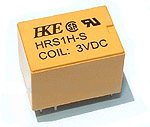
Relays
Such components exist: they are the relays. A relay is in fact an electrically activated switch: the lever is operated by an electromagnet. Current passing through the coil produces a magnetic field that is large enough to move the small contacts of the reed switch. Relays don't consume much current (they can be powered directly from TTL logic gates), and have very fast switching times. Even if they are replaced little by little by transistors in certain circuits, they are still widely used and available...Except for the low tensions such as 3V (what we need for our cars). Fortunately, it's quite easy to find such relays in Asia and many good retailers import some.I got it!
By using relays for "Forward" and "Backward" functions, the overconsumption of the circuit will be cancelled, and the engine will be connected directly to the battery pack when the order is given. Result? A surprising overspeed that could reach up to 20 km/h. The step by step guide details the modification with 2 relays (Forward and Backward) shown in the diagram on the right of this page. Watch out: this diagram is intented to cars with an upgraded gearbox. If you're using an original gearbox, you'll have to switch the two wires connected to the motor, as transmission is reversed (Forward goes Backward).
What about transistors?
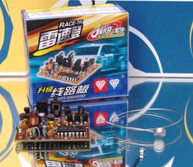
Indeed, we could use transistors (FET) instead of relays. I did not find any suitable diagram yet on this subject. Anyway, Auldey proposes as an upgrade a complete PCB based on FET (Auldey Escalate Circuitry) but only in 35MHz. Dominiz, an active member of the Mini-Zone forum sent two photographs of this circuit to me. So, if anybody want's to realize some schematics, I'll be pleased to publish them here :)
The gallery also contains pictures of a model which uses transistors...